
Synthesis of Occlusion Free Video Using a Multicamera Setup
Project Team :
Alparslan Yildiz and Dr. Yusuf Sinan Akgul.
This study focuses on a multi-view camera system that produces real-time single view scene video which sees through the static objects to observe the dynamic objects. The system employs a training phase to recover the ground homographies between views and the perspective distortion parameters. At run-time, each dynamic object is detected and automatically registered between views. The registered objects are learned using an appearance base model and later used to superimpose an occluded dynamic object on the desired view, selected as the main view.
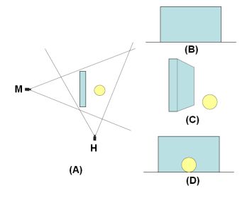 Figure on the left shows (A)
a scene containing a wall and a dynamic sphere, main camera is marked with M
and helper camear is marked with H, (B) view of the scene from the main camera,
(C) view of the scene from the helper camera, (D) "Occlusin-free" view of the
scene for the main camera.
Figure on the left shows (A)
a scene containing a wall and a dynamic sphere, main camera is marked with M
and helper camear is marked with H, (B) view of the scene from the main camera,
(C) view of the scene from the helper camera, (D) "Occlusin-free" view of the
scene for the main camera.
Occlusion detection is done using a very efficient and effective method. When an object on a helper view has a corresponding appearance on the main view, the object is said not to be occluded, otherwise occluded. Corresponding appearance, if present, is found using the ground homographies via cross-checking the ground touching points of the objects.
If an object is decided not to be occluded, the appearance of the object is registered along with the corresponding main view appearance. Later when an object, most-likely the same object, is occluded, main view appearance of the object is estimated using the previously registered appearance pairs. A match is selected such that its recorded helper view appearance is similar to the current helper view appearance. Main view appearance of the matched record is superimposed on the main view as an estimate of the object w.r.t. the p.o.v. of the main camera.
There are two issues to solve before superimposing the found match. First problem is the position where main view appearance will be superimposed. To solve this problem, an approach is transforming the ground touching pount of the object on the helper view, onto the main view. The transformed point is the estimation of position where the object would be standing if it were not occluded. Using a single helper view, the ground touching point of the object is estimated as the lowest blob point on the object vertical axis, which is a line parallel to the y axis of the image plane and passes through the mass-center of the blob. The ground touching point obtained from a single helper view is smoothed using Kalman filter or averaging over time, considering estimates both from the past and the future. With multiple helper cameras, the vertical axes of the blobs of the same object on different helper views are transformed from one view to another and the intersection is taken as the robust ground touching point. This method is also used at non-occluded time steps when recording the object appearances. The robust ground touching points of the appearances are also recorded and matching appearance is superimposed such that the recorded ground touching point and the estimation overlap.
 Second problem is the size
of the appearance to be superimposed. At the time step the appearance was
recorded, the object may have had more distance to the main camera. If the
position to superimpose the appearance is closer to the main camera, then the
appearance should be enlarged before being superimposed. The difference in
sizes of the object appearances, as they change their distance to a camera, is
related to the perspective projection laws. When projected onto the image plane,
parallel lines on a 3D plane intersect at a point called the vanishing point.
We can take the 3D ground touching point of an object and its top point,
highest 3D point w.r.t. the ground, and we can expect that when the same object
moves away from the camera, top point of the object will keep its distance to
the ground, in other words, the object's height will not change. As a result of
this, the line between the 3D ground touching points and the line between 3D
top points are parallel lines. The projections of these lines intersect at a
vanishing point where the object size would be zero if it could move that far.
In practice, we can have more than two intersections if we take each frame pair
for a single camera and track an object to find its ground touching points and
top points. These numerous intersections form a line which is called the
skyline, where the object size becomes zero. We find the sykline easily via
least-squares line-fitting to the vanishing points of a view. The skyline is
found just for the main view since the size issue is necessary only for the
main view where the superimposition will take place. Figure on the right shows
one of the intersections, for the first and last frame, and the computed
skyline. Knowing the skyline, the scaling factor of the appearance is found via
reconstructing the two intersecting lines for the recorded appearace and the
current ground touching point.
Second problem is the size
of the appearance to be superimposed. At the time step the appearance was
recorded, the object may have had more distance to the main camera. If the
position to superimpose the appearance is closer to the main camera, then the
appearance should be enlarged before being superimposed. The difference in
sizes of the object appearances, as they change their distance to a camera, is
related to the perspective projection laws. When projected onto the image plane,
parallel lines on a 3D plane intersect at a point called the vanishing point.
We can take the 3D ground touching point of an object and its top point,
highest 3D point w.r.t. the ground, and we can expect that when the same object
moves away from the camera, top point of the object will keep its distance to
the ground, in other words, the object's height will not change. As a result of
this, the line between the 3D ground touching points and the line between 3D
top points are parallel lines. The projections of these lines intersect at a
vanishing point where the object size would be zero if it could move that far.
In practice, we can have more than two intersections if we take each frame pair
for a single camera and track an object to find its ground touching points and
top points. These numerous intersections form a line which is called the
skyline, where the object size becomes zero. We find the sykline easily via
least-squares line-fitting to the vanishing points of a view. The skyline is
found just for the main view since the size issue is necessary only for the
main view where the superimposition will take place. Figure on the right shows
one of the intersections, for the first and last frame, and the computed
skyline. Knowing the skyline, the scaling factor of the appearance is found via
reconstructing the two intersecting lines for the recorded appearace and the
current ground touching point.
 Figure on the left shows
some result frames from a video sequence where a person walks behind an
occlusion. The helper camera sees the person from a different view than the
main camera but still, the main view appearance is estimated accurately.
Figure on the left shows
some result frames from a video sequence where a person walks behind an
occlusion. The helper camera sees the person from a different view than the
main camera but still, the main view appearance is estimated accurately.
A more detailed experiment of the same scenario is available here as the video output. The occlusion is manually drawn and the experiment is made with one helper camera resulting poor position estimates. The appearance estimeates, which are not too much dependent on the number of helper cameras, are quite accurate though.
Improved Multi-view Tracking
 Consider the scenario given in the figure on the right side. There are two
objects, A and B, in the scene and two cameras, C1 and C2,
viewing them from very different viewpoints. There is one
object blob from the view of C1 and two object blobs from
the view of C2. If we use only the ground homography
constraint, we have two options to solve the ambiguity of
correspondence between objects A and B in C1 and C2.
We can either transform the position of the blob on C1 to
C2 or we can transform the positions of the blobs on C2 to
C1. In both options we can check for corresponding blobs.
In the first case, if we use a transformation from C1 to C2,
we will find a position p12 that is between the blobs in C2
and this will not solve the ambiguity. In the second case,
if we use a transformation from C2 to C1, the position pB2
will appear at pB21 and the position pA2 will appear on the
outside of the image region of C1. There is an ambiguity
that we cannot determine whether the object A is visible on C1 or
not.
Consider the scenario given in the figure on the right side. There are two
objects, A and B, in the scene and two cameras, C1 and C2,
viewing them from very different viewpoints. There is one
object blob from the view of C1 and two object blobs from
the view of C2. If we use only the ground homography
constraint, we have two options to solve the ambiguity of
correspondence between objects A and B in C1 and C2.
We can either transform the position of the blob on C1 to
C2 or we can transform the positions of the blobs on C2 to
C1. In both options we can check for corresponding blobs.
In the first case, if we use a transformation from C1 to C2,
we will find a position p12 that is between the blobs in C2
and this will not solve the ambiguity. In the second case,
if we use a transformation from C2 to C1, the position pB2
will appear at pB21 and the position pA2 will appear on the
outside of the image region of C1. There is an ambiguity
that we cannot determine whether the object A is visible on C1 or
not.
We propose a novel method to track and unambiguously establish correspondences of multiple objects without relying solely on 2D ground homography. Our approach employs the fundamental matrix, F, of the epipolar geometry to introduce 3D information about the objects. With the fundamental matrix F, we can transform the top points of the blobs on C2 to C1 to find the estimated top points of the objects on C1 The top points tA2 and tB2 on C2 generates epipolar lines on C1 when transformed using F21. We use the intersection of the epipolar lines with the vertical lines passing through the transformed object positions to estimate the transformed top points. This makes it possible to detect and track occluded objects with their estimated heights on the image planes.
Using the fundamental matrix in object correspondence establishment between views increases the robustness and helps eliminate the ambiguity. Our observations showed that using the fundamental matrix with the ground homography constraint provides more reliable and unambiguous information than using the ground homography constraint alone. Intuitively, using only ground homography introduces structure information about the scene into the correspondence because homography is calculated on the ground plane. On the other hand, using the epipolar constraints on the objects introduces 3D information about the dynamic objects. Combining these two sources of information would result in better performing ambiguity resolution between views.
Results
Static occlusion (.avi)
Verification via synthetic occlusion (.avi)
Static occlusion, far object (.avi)
Improved tracking (.avi)
Dynamic occlusion (.avi)
Publications
- Alparslan Yildiz and Yusuf Akgul, "A Fast Method for Tracking People with Multiple Cameras", Third Workshop on HUMAN MOTION Understanding, Modeling, Capture and Animation, Greece, September 2010.
- Alparslan Yildiz and Yusuf Sinan Akgul. "A Multi-View Camera System for The Generation of Real-Time Occlusion-Free Scene Video", The German Association for Pattern Recognition, 2007. (Lecture Notes in Computer Science, 2007, Vol 4713) [Poster (.pdf)]