
Human Eye Gaze Estimation
Project Team: Şamil Karahan, Necmeddin Said Karakoç, Dr. Yusuf Sinan Akgül,
Estimation of human eye gaze directions is crucial for a number of areas including human computer interaction, human cognitive and emotional state analysis, and attentive user interfaces. The main problems of the estimation are 3D changing head pose and precise localization of eye centers. To solve the user head movements, we propose a new Line of Gaze (LoG) method that uses a paper target with a hole for training and simple glasses for the head tracking (in Figure 1). Both the target and the glasses are marked with fiducials for 3D localization. The system does not need any extra cameras or IR light sources.
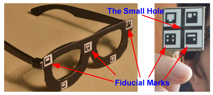
Figure 1: Left: the modified3D movie glasses, right: the target.
Figure 2 shows the general 3D geometry of our LoG estimation system, which includes a 3D glass coordinate system. The point correspondences between the camera space S_C^i and the glasses space S_G are estimated using the detected fiducial positions on the images and the known 3D fiducial positions on the glasses. A plane is formed by using the known 3D positions of O_C^i, l_C^i and h_C^i. The plane also intersects the stable 3D position of cornea center E_G. We need a few view instants to locate the center by intersecting the defined planes. The gaze direction is estimated by using the unit vector which lies between E_G and H_T^i.

Figure 2: The 3D Geometry of Line of Gaze (LoG).
The preciese eye localization is crucial for eye gaze estimation. There are several types of methods for pupil center localization. One of these types uses specialized hardware such as head-mounted devices or multiple near-infrared cameras. But these methods are expensive, uncomfortable, intrusive, and generally require a calibration stage. Recently, appearance based pupil center localization methods, which need only webcam type cameras, started addressing the above problems. We propose a new model based approach for accurate and robust pupil center localization on images supplied from a monocular camera system. We argue that the gradient angle information around the eye pupil region has a unique signature (see the extracted HOGs in Figure 3 and Figure 4) and employing HOG technique as the basic feature extraction tool should capture this information.
The proposed system consists of two phases: training and testing. To train the model (Figure 3), we use k training windows around the eye regions (T_1, T_2,…., T_k). The window sizes are chosen much larger than the eye region to make the final trained regressor robust against eye detector errors. About 30 patches (P_1^n, P_2^n, ….P_30^n) are randomly sampled from each T_n. The sizes of these patches are 96 x 96. Suppose patch P_O contains the pupil center at the patch center (such as P_2^n in Figure 3). We like to learn a function y(.) such that y(f(P_O)) produces maximum value where f is a function for extracting feature vectors from the image patches. The value of the function y decreases proportional to the Euclidian distance between the patch center and the pupil center. For example, y(f(P_30^n)) would produce the smallest value and y(f(P_2^n)) would produce the largest value for the patches of Figure 3. We propose to learn the function y using the SVR method. To train the SVR model, we need input patterns, which are the image features produced by the function f. In our case, the function f produces HoG vectors for the given patch. SVR training also needs the targets for each input pattern. To provide this target data to the SVR model, we calculate the Euclidian distance d_r^n between the center of the patch P_r^n and the pupil center. The calculated distance values are fed to an exponential function t whose values rapidly increase around the pupil centers, which makes the overall localization problem more accurate. We observed that training a polynomial SVR model with the target values from function t (instead of d_r^n) produces much better results for the task of pupil center detection. The function f takes an image patch P_r^n and produces HoG vector 〖PH〗_r^n. Finally, the vector V_r^n is formed by combining the input pattern 〖PH〗_r^n with the target t(d_r^n). The SVR model is trained with all V_r^n vectors, where n=1,2,..,k and r=1,2,..,30. The proposed work trains only one regressor model for both eyes by flipping the left eye horizontally to make it act like the right eye. Based on our experiments, we observe that using a third degree polynomial kernel for the regressor outperforms alternative kernels.
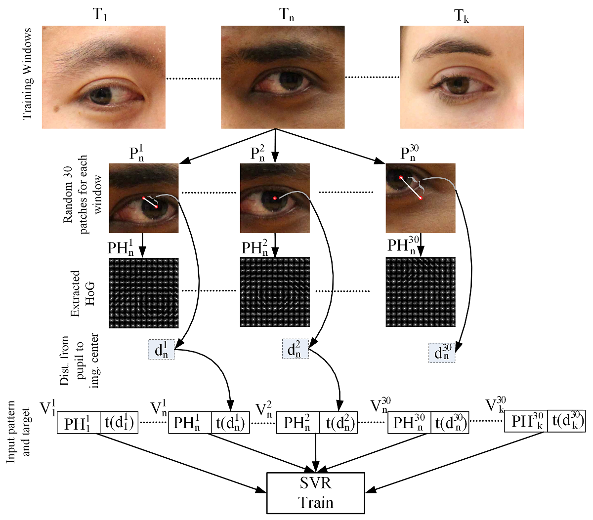
Figure 3: Training stage of the proposed method.
In the test stage, first approximate face and eye positions are obtained (Figure 4). We fix the size of the pupil center search areas (Figure 4, E_L and E_R) proportional to the detected distance between the left and right eyes. The eye region E_L is scanned to produce sliding windows S_L^1 to S_L^m, where m is the number of sliding windows in eye region E_L. Each sliding window S_L^n is scaled to 96 x 96 pixels similar to the scaling process done in the training phase. We then produce the HoG vector 〖SH〗_L^n for each S_L^n. The vector 〖SH〗_L^n is fed to the trained SVR to produce the estimated exponential distance to the pupil center for each S_L^n. The same process is repeated for the other eye region E_R. A score image is formed by using the regressor results which visually shows where the pupil centers are located (Figure 4).
We employ a two stage approach for the scanning window process. First, we start from the top-left corner and slide the window by skipping 5 pixels. The regressor response is calculated for each sliding window S. The maximal response areas are then scanned again with 1 pixel window skipping. Thus, we reduce the search time considerably. For the final estimation, our method selects the best 20 positions on the score image. Second degree polynomials are fit around these maximal points on the score image. We calculate the zero value of the first derivative of the polynomials to find the pupil center. Our task of estimating the pupil centers is for both eyes, thus we run a special algorithm that finds the pupil centers of both eyes simultaneously. Out of the best 20 positions on the score image of both eyes, we chose the best combination that produces best total score within a minimum and maximum Euclidian separation. As a result, eye centers that have too close or too far positions are eliminated.
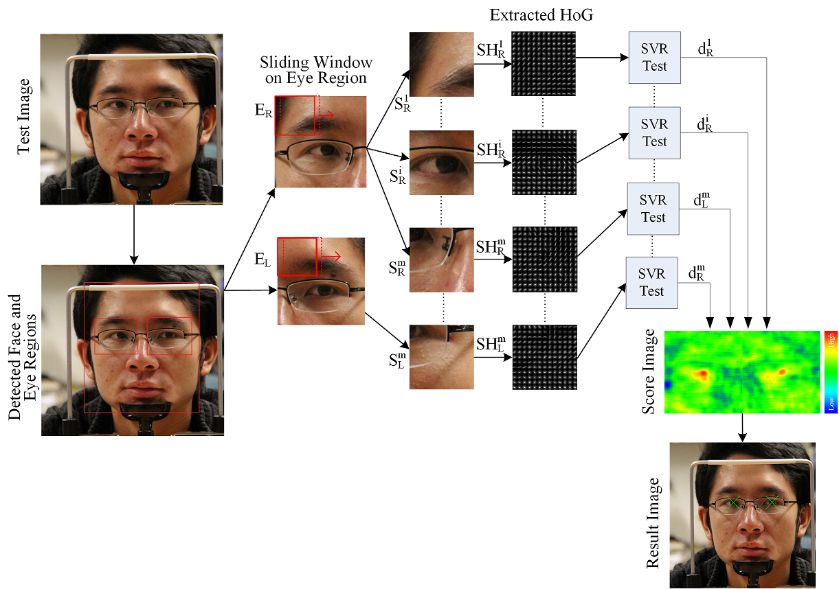
Figure 4: Test stage of the proposed method.
Test results on BioID and CAVE set can be downloaded from here (99,5 mb).
Publications
- Samil Karahan,Yakup Genc, Yusuf Sinan Akgul, "A New 3D Line of Gaze Estimation Method with Simple Marked Targets and Glasses", 3rd International Workshop on Pervasive Eye Tracking and Mobile Eye-Based Interaction, ECEM, Lund, August 2013.
- N. S. Karakoc, S. Karahan and Y. S. Akgul, "Iterative Estimation of The Eye Pupil Center," in Signal Processing and Communications Applications Conference (SIU), Malatya, Turkey, in Turkish, 2015.
- N. S. Karakoc, S. Karahan and Y. S. Akgul, "Regressor Based Estimation of The Eye Pupil Center," 37th German Conference on Pattern Recognition (GCPR 2015) , Aachen, Germany, 2015.